Yenka PICs is an exciting free flowchart application for developing PICAXE programs. PICAXE microcontroller flowchart programs can be developed on Windows, Mac and Linux via use of Flowol. Free add-on for Programming Editor, Logicator and all other Windows applications. Print your BASIC programs and flowcharts to colour PDF file. PICAXE PDF Printer Driver PDFPrinter FREE PICAXE command line console compilers for integrating into your own software application. This is the Prolific driver for the USB to Serial Adapter (part USB010). USB010 USB Adapter Driver USB010_driver FREE This is the latest driver for the PICAXE USB Download Cable (part AXE027). DownloadĪXE027 USB Cable Driver AXE027_USB_Driver FREE

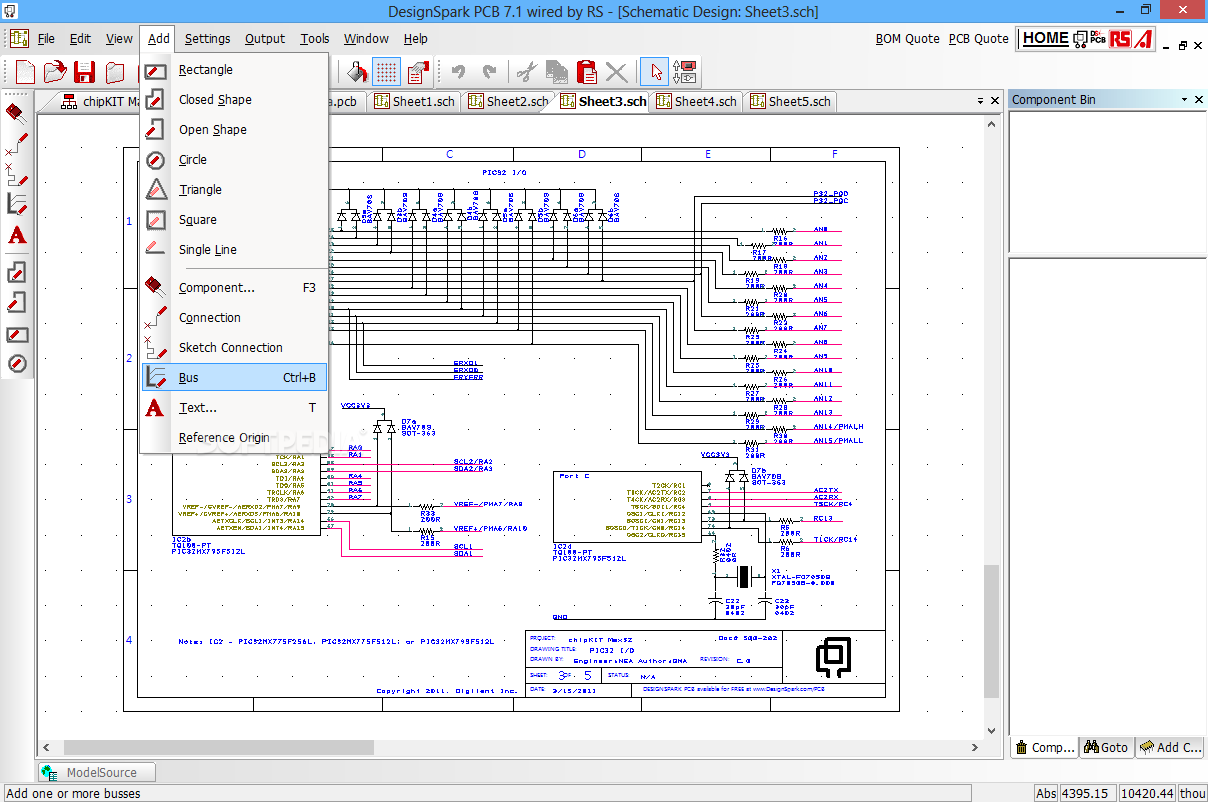
PICAXE Virtual System Modelling (VSM) is a software circuit simulator, that combines a ‘virtual’ PICAXE chip with animated components and Berkeley SPICE circuit analysis to produce a simulation of a complete PICAXE project. It supports BASIC programming of PICAXE chips on all of the Windows, Mac and Linux operating systems. DownloadĪXEpad is a cross-platform development tool for PICAXE chips. Visual block and text programming for PICAXE on any computer platform. PICAXE Editor 6 is the recommended Windows software for programming, testing and simulating BASIC, Blockly and flowchart programs for PICAXE. For more information see the Getting Started - Software Selection page. PICAXE chips may be programmed via the official PICAXE software (in BASIC or flowcharts) or by various third party approved products. These standard files are accepted by PCB fabrication companies and are used to build a printed circuit board.Official Software for use with PICAXE projects Components can also be auto-placed.ĭesignSpark PCB produces Gerber and Excellon drill files. A design may have several iterations before a finalised printed circuit board is passed for production.ĭesignSpark PCB includes an auto-router which automatically places tracks between components on a PCB layout. A PCB layout editor is then used to refine the physical layout of the printed circuit board. Schematics are translated to a PCB layout file with a PCB Wizard. There are some useful third party libraries that can be added. A given project can have multiple schematic sheets that together combine to form the complete design.

Schematics are used to draw up circuit diagrams and connections.

A project can have an unlimited number of schematic sheets and one PCB layout file.ĭesignSpark PCB has a Schematic editor. Projects are used in DesignSpark PCB to organise design files. DesignSpark resulted from a collaboration between electronics distributor RS Components and EDA software developer Number One Systems.


 0 kommentar(er)
